An O-ring is a torus, or doughnut-shaped ring, generally molded from an elastomer, although O-rings are also made from PTFE and other thermoplastic materials, as well as metals, both hollow and solid. This handbook, however, deals entirely with elastomeric O-rings.
O-rings are used primarily for sealing. The various types of O-ring seals are described in this section under “Scope of O-Ring Use.” O-rings are also used as light-duty, mechani- cal drive belts. More information, including design criteria on O-ring drive belts and their application will be found in O-Ring Applications, Section III.
An O-ring seal is used to prevent the loss of a fluid or gas. The seal assembly consists of an elastomer O-ring and a gland. An O-ring is a circular cross-section ring molded from rubber (Figure 1-1). The gland — usually cut into metal or another rigid material — contains and supports the O-ring (Figures 1-2 and 1-3). The combination of these two elements; O-ring and gland — constitute the classic O-ring seal assembly.

Figure 1-1: Basic O-Ring
• They seal over a wide range of pressure, temperature and tolerance.
• Ease of service, no smearing or retightening.
• No critical torque on tightening, therefore unlikely to cause structural damage.
• O-rings normally require very little room and are light in weight.
• In many cases an O-ring can be reused, an advantage over non-elastic flat seals and crush-type gaskets.
• The duration of life in the correct application corresponds to the normal aging period of the O-ring material.
• O-ring failure is normally gradual and easily identified.
• Where differing amounts of compression effect the seal function (as with flat gaskets), an O-ring is not effected because metal to metal contact is generally allowed for.
• They are cost-effective and widely used in various of Hydraulic Pump, Hydraulic Motor and other hydraulic sealings.
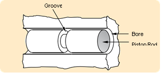
Figure 1-2: Basic Gland
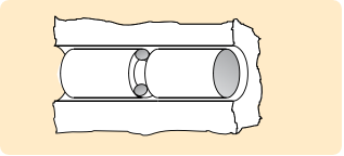
Figure 1-3: Gland and O-Ring Seal
All robust seals are characterized by the absence of any path- way by which fluid or gas might escape. Detail differences exist in the manner by which zero clearance is obtained — welding, brazing, soldering, ground fits or lapped finishes
— or the yielding of a softer material wholly or partially confined between two harder and stiffer members of the assembly. The O-ring seal falls in the latter class.
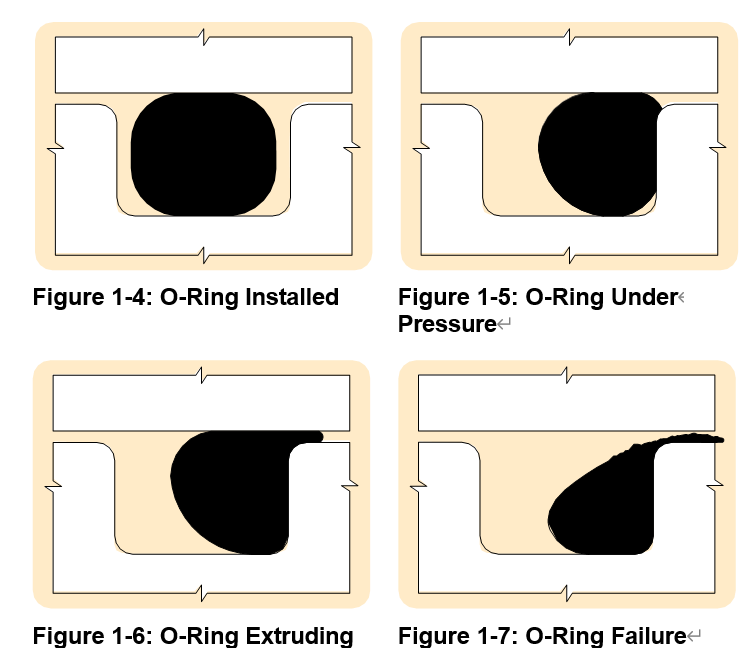
The rubber seal should be considered as essentially an incompressible, viscous fluid having a very high surface tension. Whether by mechanical pressure from the surrounding structure or by pressure transmitted through hydraulic fluid, this extremely viscous fluid is forced to flow within the gland to produce “zero clearance” or block to the flow of the less viscous fluid being sealed. The rubber absorbs the stack-up of tolerances of the unit and its internal memory maintains the sealed condition. Figure 1-4 illustrates the O-ring as installed, before the application of pressure. Note that the O-ring is mechanically squeezed out of round between the outer and inner members to close the fluid passage. The seal material under mechanical pressure extrudes into the microfine grooves of the gland. Figure 1-5 illustrates the application of fluid pressure on the O-ring. Note that the O-ring has been forced to flow up to, but not into, the narrow gap between the mating surfaces and in so doing, has gained greater area and force of sealing contact. Figure 1-6 shows the O-ring at its pressure limit with a small portion of the seal material entering the narrow gap between inner and outer members of the gland. Figure 1-7 illustrates the result of further increas- ing pressure and the resulting extrusion failure. The surface tension of the elastomer is no longer sufficient to resist flow and the material extrudes (flows) into the open passage or clearance gap.
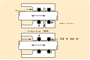
A very early and historically prominent user of O-rings(1) cites a number of characteristics of O-ring seals which are still of interest to seal designers. Extracts of the more general characteristics are listed as follows:
Note: While Parker Seal generally agrees with the author on most of his statements, exception will be taken to certain generalizations due to more recent developments in sealing geometry and improved elastomer technology.
A. The seals can be made perfectly leak-proof for cases of static pistons and cylinders for fluid pressures up to 5000 psi. (Limit of test pressure). The pressure may be constant or variable.
B. The seals can be made to seal satisfactorily between re- ciprocating pistons and cylinders at any fluid pressure up to 5000 psi. There may be slight running leakage (a few drops per hundred strokes) depending on the film-forming ability of the hydraulic medium. O-rings can be used between rotating members with similar results but in all cases the surface rubbing speed must be kept low.
C. A single O-ring will seal with pressure applied alternately on one side and then on the other, but in cases of severe loading or usage under necessarily unfavorable conditions, seal life can be extended by designing the mechanism so that each seal is subjected to pressure in one direction only. Seals may be arranged in series as a safety measure but the first seal exposed to pressure will take the full load.
D. O-ring seals must be radially compressed between the bottom of the seal groove and the cylinder wall for proper sealing action. This compression may cause the seal to roll slightly in its groove under certain conditions of piston motion, but the rolling action is not necessary for normal operation of the seals.
E. In either static or dynamic O-ring seals under high pressure the primary cause of seal failure is extrusion of the seal material into the piston-cylinder clearance. The major factors effecting extrusion are fluid pressure, seal hardness and strength, and piston-cylinder clearance.
F. Dynamic seals may fail by abrasion against the cylinder or piston walls. Therefore, the contacting surfaces should be polished for long seal life. Moving seals that pass over ports or surface irregularities while under hydraulic pressure are very quickly cut or worn to failure.
G. The shape of the seal groove is unimportant as long as it results in proper compression of the seal between the bottom of the groove and the cylinder wall, and provides room for the compressed material to flow so that the seal is not solidly confined between metal surfaces.
H. The seal may be housed in a groove cut in the cylinder wall instead of on the piston surface without any change in design limitations or seal performance.
Click to download the complete handbook "About O-Rings".
Contact: Frank Xie
Phone: +86-18951952293
Tel: +86-25-83408096
Email: sales@super-hyd.com
Add: 97#, Luxiying, Gulou Dis, Nanjing, China.
We chat
